FPGA Design Overview
The FPGA had a couple of tasks that were laid out by our project proposal. One of the tasks was to control the light display. While the original plan was to get the light code sequence from SPRAM, we did not get to this point due to unforeseen circumstances. We were able to program it with a given RGB color string and used an FSM to shift the lights in different patterns. The FPGA also controlled the servo motor that moved the “needle” of our jukebox. This was also controlled by an FSM. The servo motor design fully met our specs.
Block Diagram
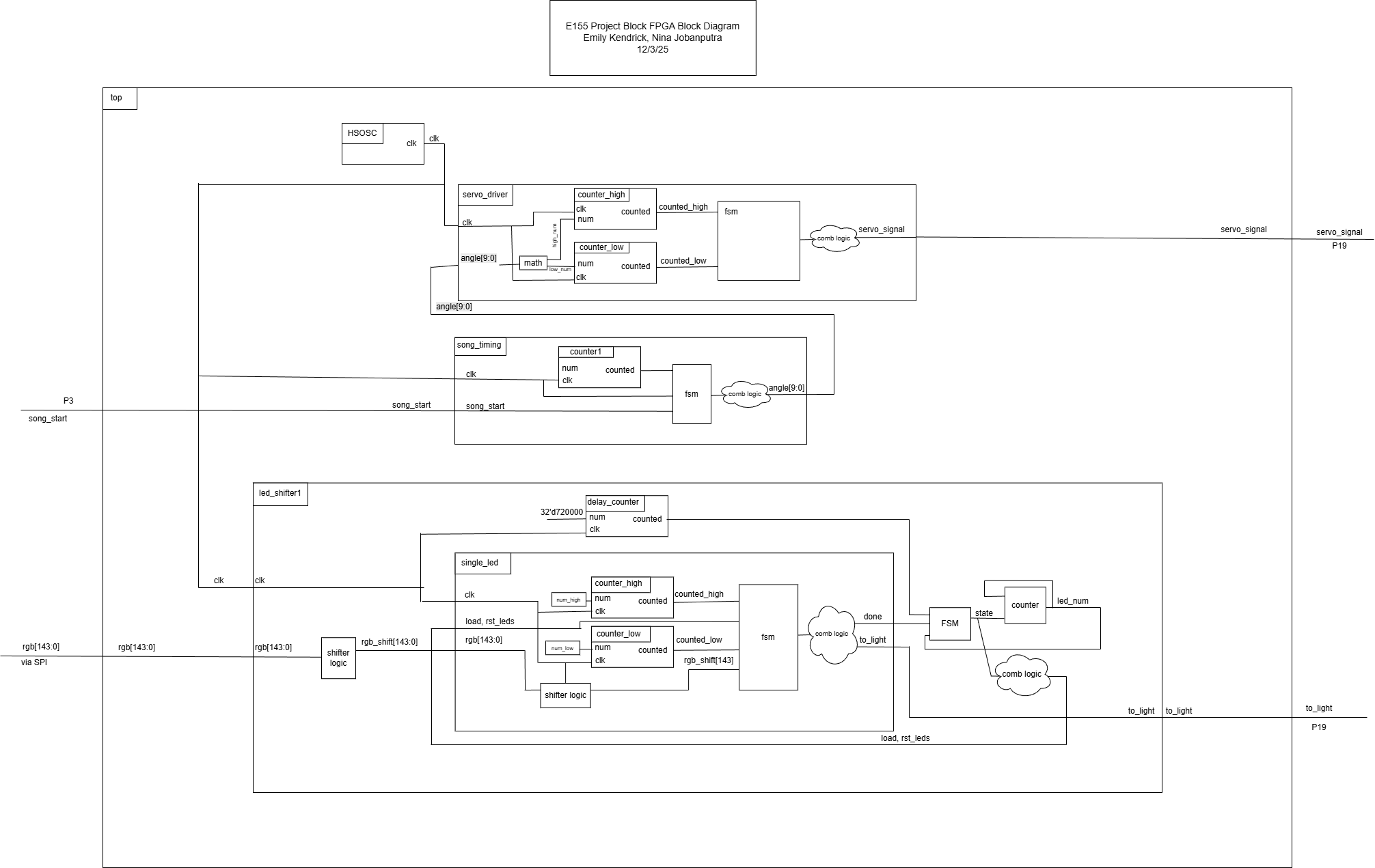
The block diagram for our FPGA design is given below.
LED Strip Control
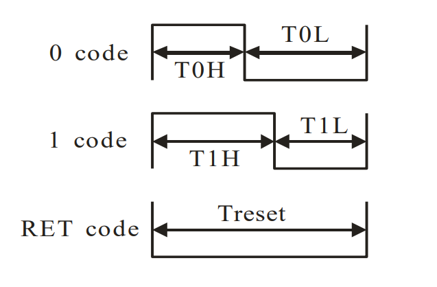
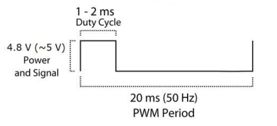
The FPGA displayed a custom color sequence on a WS2812 RGB individually addressable LED strip with 144 pixels/m. The data transfer protocol for the LEDs is NZR, non-return-to-zero communication. This involved sending a PWM signal and changing the duty cycle of the pulses based on the data to be sent, like in the diagram below.
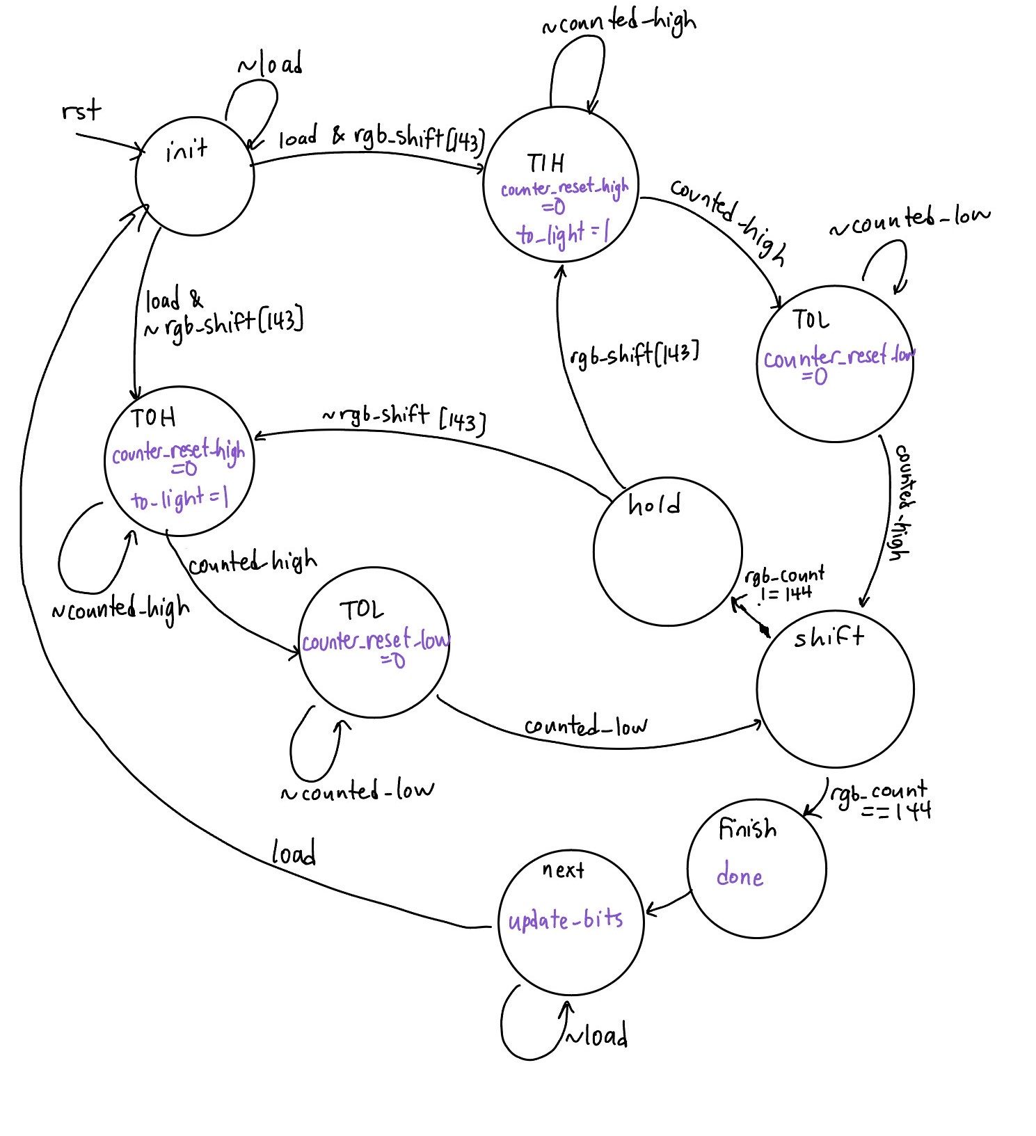
This was accomplished using two FSMs: led_driver and led_shifter. led_driver shifted in a specific number of bits to the LED strip by updating the duty cycle of the PWM signal for each bit. To save on space, a pattern of 6 colors was repeated across the entire LED strip, so this took 144 bits (corresponding to 6 LEDs * 24 bits each). Each LED requires 24 bits (8 green, 8 red, 8 blue).
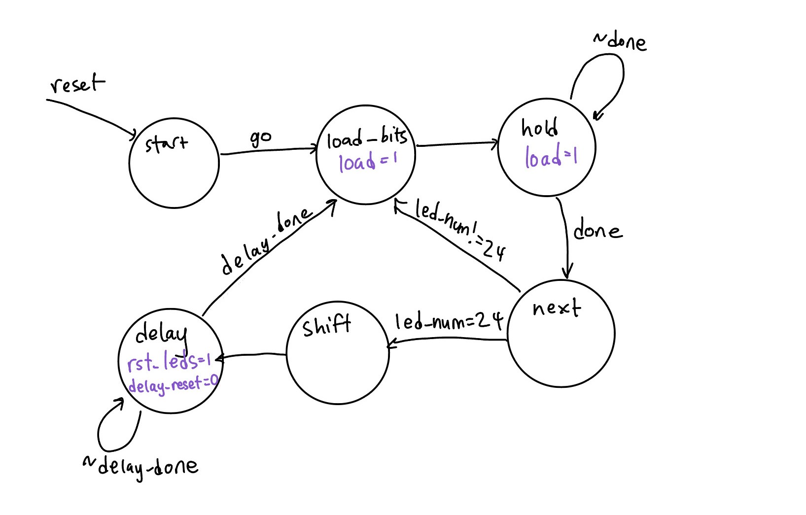
led_shifter iterates through inputs to be sent to the led_driver. The same 144 bit string is sent to the LED strip 6 times over, then a reset signal is asserted (which just requires pulling the output pin low for at least 50 microseconds). The original string is shifted by 24 bits so it looks like the colors are “sliding” across the LEDs. This was successfully implemented, but no video was taken before all of the hardware broke.
Servo Control
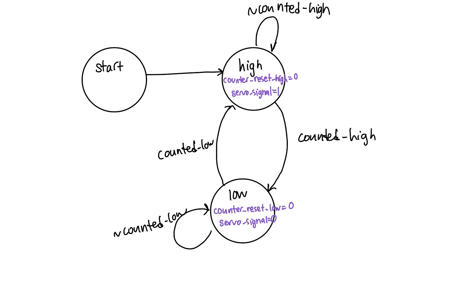
The servo was implemented to control a “needle” that would lay on top of the “record” to look like a real jukebox. An SG90 servo motor was used, which takes a PWM input with a duty cycle corresponding to the angle the servo should turn to. The PWM signal has a period of 20ms. An angle of -90 degrees requires a pulse width of 1 ms, an angle of 0 degrees requires a pulse width of 1.5 ms, and an angle 90 degrees requires a pulse width of 2.0 ms.
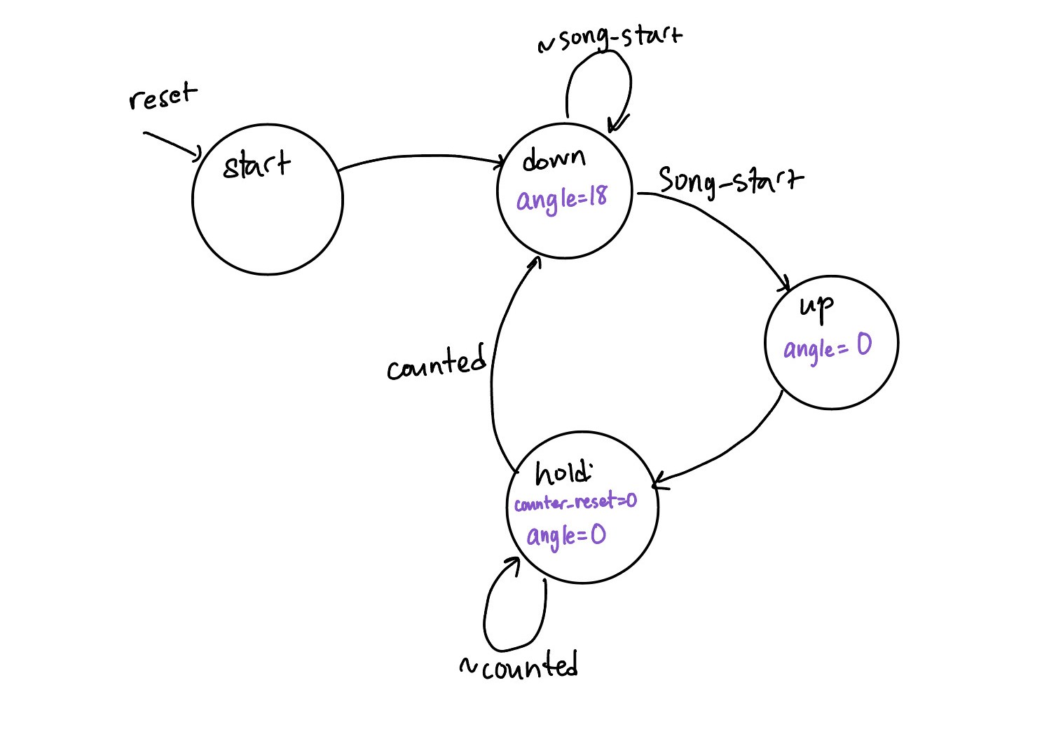
This was achieved using two FSMs and counters. servo_control outputs the PWM signal based on an input angle, and just makes use of counters. song_timing asserts angles corresponding to a down, then up, then back down position when a song is loaded to simulate changing a record.
SPRAM
The new feature we tried to implement on the FPGA was of SPRAM. In our original design we wanted the FLASH of the MCU to transmit data to the SPRAM of the FPGA via SPI to store color data for the lights. While we had code that would upload the SPI transmitted bits to the SPRAM and it was able to synthesize we never got a chance to test it before our project ended up getting shorted.