Results
Results Overview
At some point in time, the design successfully read the ID of an RFID tag and used that information to select a song from an SD Card inserted in a DFPlayer. Further, the MCU was able to store color data in FLASH that could be read and sent via SPI to the FPGA. The FPGA was also able to play a “light show” on the LED string, updating in such a way that the colors were “sliding” across the string. Then, disaster struck. During testing, power and ground were shorted to one another, destroying our entire project. It was going to be cool, but you’ll just have to take our word for it.
Specs and Performance
The following were our specs at the beginning of the project and whether or not we met them.
- RFID reader is able to correctly identify unique cards and select current song from SD card memory
- Status: met
- The RFID reader successfully communicated via SPI and identified unique RFID tags.
- MCU is able to write to SPRAM of the FPGA via SPI.
- Status: unmet
- The FLASH memory of the MCU was successfully written to and transmitted out via SPI. However, we were unable to test the SPRAM of the FPGA before our hardware broke.
- DFPlayer can use song data to play songs on speaker.
- Status: met
- The DFPlayer could read songs from an SD card and play them.
- FPGA can communicate with external LEDs and motors to play a light show during the song with a synchronized start time.
- Status: met
- A PWM signal was used to communicated with both LEDs and the servo. Both worked before hardware issues.
- Needle lowers at start of song, play back should start after needle lowers, and light show begins.
- Status: eh
- The servo moves at the start of the song, and the LEDs start shifting at the beginning of a song. However, we never added a “needle” to the servo.
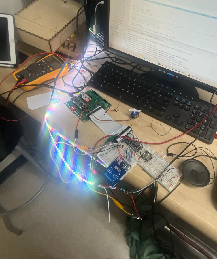
System images and videos
Tragedy strikes!
During the process of creating this project, power and ground were accidentally shorted together while moving all the components from a small breadboard to a larger one. All of the external components and the FPGA were fried. The MCU is the only part that lives to see today. As a result, the pictures and videos we have are limited.
Lights
While we were able to successfully program the lights so it looked like a pattern of lights was “shifting” across the string, we do not have a video of that working. Instead, we have this video of the lights blinking two different colors, and a picture of a rainbow string.
DFPlayer
We also have a video of the DFPlayer playing a song. We do not have a video of the RFID Reader working.
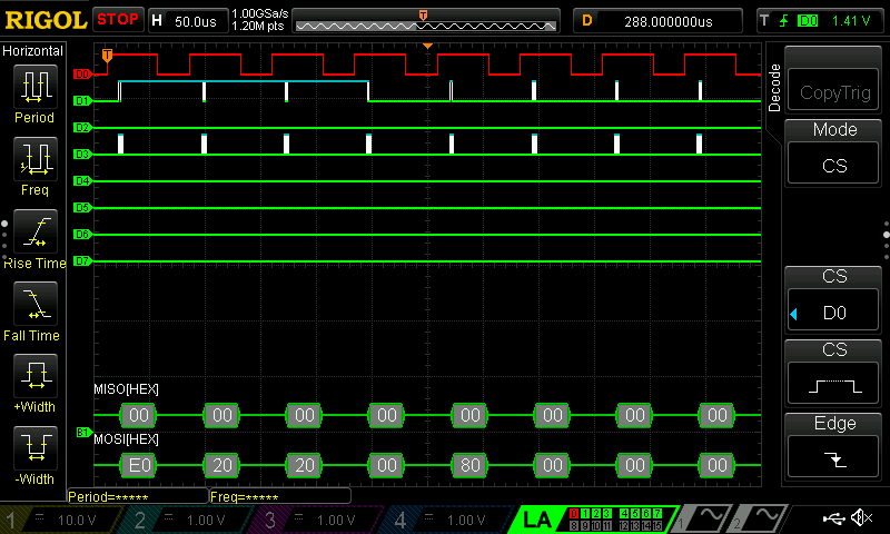
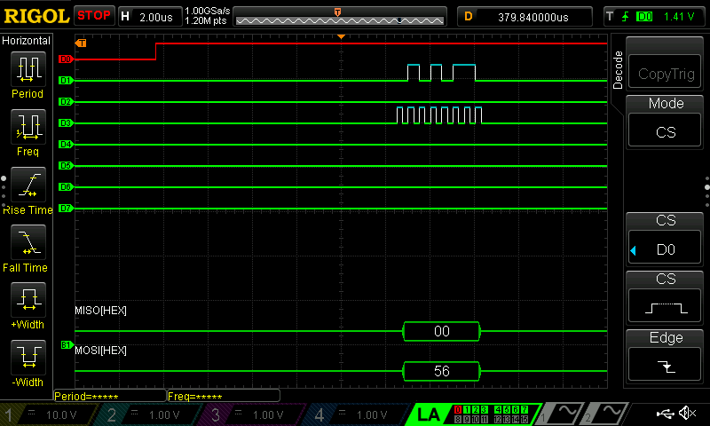
Logic Analyzer and Testbench Results
The logic analyzer and Quarto simulator were used extensively for testing software. The logic analyzer was used for verifying communication with the DFPlayer and SPI communication from the MCU (which was supposed to go to the FPGA). Results from the logic analyzer are given below.
The Quarto simulator was used to verify the FSMs were behaving as expected. Their results are given below. The led_driver module was made to modulate the duty cycle of a PWM signal to send to the lights. The waveforms indicate that it is behaving as expected. 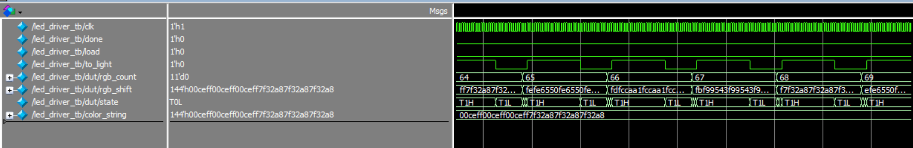
The led_shifter module was made to shift strings into the led_driver module. Here, after 24624 bits of data has been sent to the LEDs, a reset signal is sent and the RGB string to be sent to the LED strip is shifted. 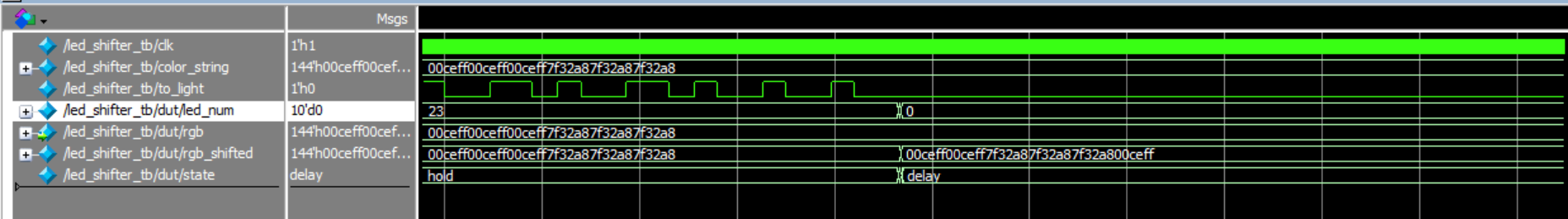
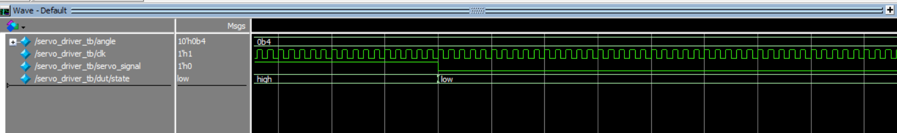
The servo_driver module created a PWM signal for the servo based on an input angle. Here, the output shifts from high to low.